Table of Contents
What is this?
Lightkraken is a PoE++ (802.3bt Type 4) powered LED strip driver.
- Up to 70W of power+data through a single standard Cat5 network cable
- Supports ArtNet and E1.13 protocols
- Supports most common programmable strips (WS2812b, APA102 etc.) or can drive analog RGB(W) strips using PWM at 14 bit resolution
- 5V/12V/24V output selectable with a switch
- web configurator built into device
PoE Power
Fully compatible with switches which support the following PoE standards:
- 802.3bt Type 4 “PoE++” (70W max)
- 802.3bt Type 3 “4PPoE” (50W max)
- 802.3at Type 2 “PoE+” (25W max)
- 802.3af (802.3at Type 1) “PoE” (12.5W max)
Implementation
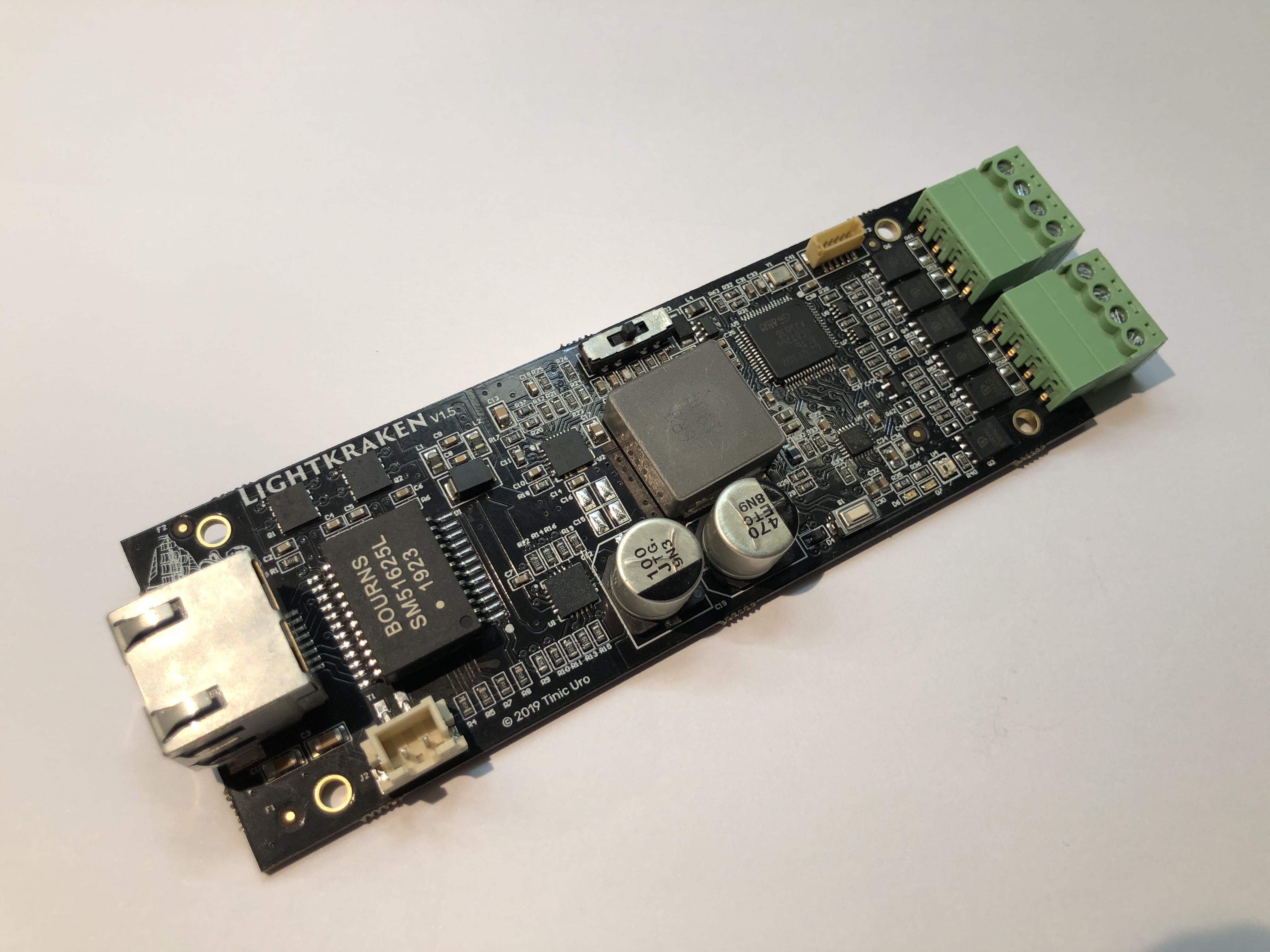
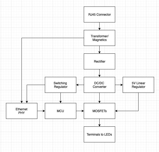
The PoE section of the Lightkraken board is based on a Bourns SM51625EL transformer and Texas Instruments TPS2372 PoE PD interface. It is rated for 70W of power, or 1.2A at the input.
The rectifier uses two Fairchild FDMQ8205A MOSFET bridge ICs. During prototyping it was determined that using Schottky or regular diodes (to reduce cost) for the rectifier section generated too much heat. The use of the FDMQ8205A part is recommended in the Texas Instruments application notes.
Output power modes
- 5.4V @ 10A (54W)
- 12V @ 5.8A (70W)
- 23.5V @ 3A (70W)
There is a 3-position switch on the board which allows the selection of the output voltage. Left position is 5.4V, middle is 12V and right position is 23.5V.
5.4V was selected instead of 5V to slightly extend the physical range of addressable LEDs without color change due to voltage drop. Virtually all LED chips rated for 5V also support 5.4V without any negative effects.
If you drive your LEDs at 25W or higher it is recommended to install a fan as the DC/DC conversion section on the board can become rather hot without one (I measured 100C/212F in open air, this will be much higher in an enclosed space). The board comes with a standard JST XH2.54-2P fan header, readily available 30x30x10mm fans work fine.
Implementation
The DC/DC converter section of the Lightkraken board uses a Vishay SiC461 DC/DC Converter. It is rated for 10A of power. The inductor is an oversized TAITEC 6.8uH part, rated for up to 22A.
Networking
- 100/10Mbit ethernet
- single RJ45 connector
- DHCP (default) or static IP address. IPv4 only.
- Each device has a unique MAC (LAA) address and host name
- Each device has a built-in web configuration page. No public internet connection is required.
- ArtNet and E1.31
- Each device supports up to 5 universes per output. For RGB strips that means up to 1020 LEDs per output (see “Reality Check” below)
- Accepts unicast or broadcast ArtNet packets
- Accepts unicast E1.31 traffic and joins E1.31 multicast address space by default
- Supports ArtNet and E1.31 synchronization packets
Implementation
The ethernet interface uses a LAN8720A IC which operates in RMII mode only.
The microcontroller is a GigaDevice GD32F107RCT6 Cortex-M3 part. The part was chosen because of physical package size, RAM size and low cost. Unfortunately ST does not provide an equivalent part, 64KB of RAM is way too small for this application. LwIP, the TCP/IP stack used, consumes about 50KB of RAM alone in the latest version which leaves little room for client code. Lightkraken needs about 32KB RAM to be able to drive LED strips using DMA.
Unique MAC addresses are generated by computing a 32-bit hash of the UID of the microcontroller and using a fixed LAA prefix.
Data input modes
- RGB 8-bit sequential DMX data. RGB is automatically converted to RGBW if such a strip is used.
- RGBW 8-bit sequential DMX data. RGBW is automatically converted to RGB if such a strip is used.
- sRGB 8-bit sequential DMX data. This will convert the received data using the reverse sRGB transfer function (“gamma correction”).
Data output
There are 4 data lines which can either drive two 1-Wire or two serial data (Clock+Data) signals at 5V TTL.
If the device is configured for Analog RGB mode some of the data lines are hard-rewired to Power MOSFETs instead of to the internal 5V TTL voltage and can drive up to 6A of power.
Implementation
The data lines are connected to the SPI peripheral pins of the MCU. The MCU does output LED data using DMA+SPI.
The data output pins on the terminals are driven using real 5V TTL through a MOSFET based level shifter. There is a dedicated linear regulator which provides 5V, derived from the voltage the DC/DC converter does output. So even with long cables there should be no signal dropout because of a voltage drop.
All data output lines have a 500 Ohm impedance matching resistor in line. This resistor was chosen to handle the most common LED strip setups. In specific cases this 0603 sized resistor might not be appropriate and has to be customized.
Note: Do not use consume any significant current on the 5V data lines. The linear regulator can only handle a few millamps before it goes into thermal shutdown.
Reality check
54W@5V and 70W@12V is not a lot in the grand scheme of things. While Lightkraken supports up to 5 universes per output, don't expect to be able to drive LEDs at full brightness using this configuration. Realistically expect 1 universe (~256 LEDs) per Lightkraken device at full brightness. I have tested one of these](https://www.amazon.com/gp/product/B07417BRFN) successfully on a POE-171A-95 switch for several weeks. YMMV will vary of course as all LEDs out there vary in specifications.

